
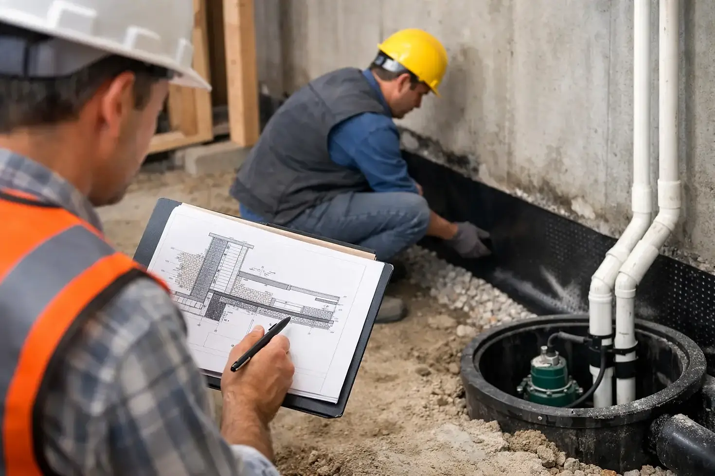
Basement Waterproofing Coordination Guide for Projects
- Ahmad Samadi
- Jul 26
- 6 min read

Water ingress below ground is rarely caused by one isolated design decision. It is more commonly the result of an uncoordinated interface: a membrane interrupted by a pile cap, a drainage line that cannot be maintained, a construction joint treated differently by two trades, or a change in groundwater conditions that was not carried through to the final design. This basement waterproofing coordination guide outlines how project teams can manage those interfaces from early investigation through to handover.
For developers, builders, asset owners and public-sector delivery teams, basement waterproofing is not a finishes issue. It is a whole-of-project performance requirement affecting structural durability, occupant amenity, programme certainty, operational cost and, in some cases, the functionality of critical infrastructure.
Start with the ground model, not the membrane
An effective waterproofing strategy begins with a sufficiently developed understanding of the site. Geotechnical investigation should establish soil and rock profiles, groundwater levels, perched water potential, hydraulic behaviour, contamination considerations and the likely effects of excavation on adjacent assets. A single groundwater reading is not necessarily representative. Seasonal variation, rainfall events, nearby drainage infrastructure and tidal influence in some locations can materially alter conditions.
The design team should convert this information into clear design assumptions. Is the basement expected to resist hydrostatic pressure? Can pressure relief drainage be relied upon over the life of the asset? Is temporary dewatering required, and could it affect neighbouring foundations or services? These questions determine the appropriate waterproofing philosophy.
In Australian practice, the waterproofing system must be selected with the intended basement use in mind. A plant room, car park, archive storage area and habitable space do not have the same tolerance for moisture. The required level of dryness, permissible maintenance access and consequence of failure should be agreed early, rather than assumed after the structural scheme is fixed.
Establish one coordinated waterproofing strategy
Waterproofing should be documented as an integrated strategy, not dispersed across architectural, structural, civil and hydraulic drawings. The strategy should define the system type, design water conditions, key interfaces, inspection points, testing requirements and responsibilities for design, installation and protection.
A combined approach may be appropriate for complex sites. This can include a watertight reinforced concrete structure, external sheet or liquid-applied membranes, waterbars at joints, injection hoses at high-risk construction joints, subsoil drainage and maintainable collection points. Redundancy can improve resilience, but it can also create confusion if components are specified without a clear hierarchy of performance.
The project team needs to be explicit about what each layer is intended to do. For example, a drainage system may reduce water pressure but should not be treated as a substitute for a structure designed to tolerate the credible groundwater condition. Likewise, a membrane may manage external water but cannot compensate for uncontrolled cracking, poor joint detailing or penetrations installed without approved seals.
Define accountability at every interface
Many failures arise where work packages meet. Structural engineers typically determine wall, slab, joint and crack-control requirements. Geotechnical engineers define ground and groundwater parameters. Architects coordinate spatial constraints and the required internal environment. Hydraulic and civil engineers address external drainage, discharge and access. The waterproofing designer and specialist contractor then translate these requirements into a buildable system.
These roles must be coordinated before construction documentation is issued. A responsibility matrix is particularly valuable for identifying who designs, supplies, installs, inspects and signs off each element. It should cover construction joints, movement joints, penetrations, lift pits, service trenches, retaining-wall terminations, capping beams, podium interfaces, temporary anchors and interfaces with existing structures.
Responsibility should not be blurred by generic notes stating that waterproofing is to be undertaken by others. Those notes leave the project exposed precisely where technical judgement is required.
Coordinate structure, services and drainage early
Basement structure and waterproofing are inseparable. Wall thickness, reinforcement congestion, pour sequence, allowable joint locations and the detailing of slab-to-wall connections can all influence the practical installation and long-term performance of the system. The structural design should consider expected crack widths, restraint, shrinkage, thermal effects and movement compatibility with any bonded membrane.
Service penetrations require equal attention. Penetrations should be minimised, grouped where practical and located away from joints, re-entrant corners and areas of high reinforcement congestion. Each penetration needs a specified sealing arrangement that suits the service type, movement expectation and anticipated water pressure. Late penetrations, often introduced to resolve services coordination during construction, are a recurring source of defects because they bypass the original waterproofing detail.
Below-ground drainage must also be treated as an asset, not merely a construction detail. Filter compatibility, drainage capacity, falls, clean-out access, inspection chambers, sump capacity, pump duty and standby arrangements all affect whether the system can perform over time. Where pumped drainage is part of the strategy, the owner must understand the operational obligations, including power resilience, alarms, inspection and maintenance.
Use design reviews to resolve high-risk details
A targeted interdisciplinary review is more effective than a broad drawing check. The review should focus on locations where geometry, sequencing or access makes standard details unreliable. Typical high-risk areas include changes in level, deep lift pits, ramp thresholds, retaining-wall returns, basement-to-podium transitions, expansion joints, crane bases, temporary works connections and interfaces with existing buildings.
Three-dimensional coordination can be useful, particularly on dense urban sites where structural framing, hydraulic services and temporary works compete for the same space. However, a coordinated model does not itself prove waterproofing performance. Teams still need to confirm that membranes can be installed continuously, that laps and terminations are accessible, that protection can be placed without damage and that drainage outlets remain serviceable.
Where proprietary systems are proposed, the specified system should be reviewed against actual site conditions and project geometry rather than accepted on product literature alone. Compatibility between primers, membranes, sealants, waterbars, protection boards and repair materials should be verified. Substitutions require the same level of review, especially where they affect bond, elongation, chemical resistance or installation sequence.
Build sequencing into the design
Waterproofing failures frequently begin before the final membrane is applied. Excavation support, shotcrete, anchor heads, blinding quality, reinforcement placement and concrete pours can each compromise continuity or restrict access. Construction methodology must therefore be developed alongside the design.
The builder should prepare hold points for substrate acceptance, membrane installation, joint treatment, penetration sealing, protection-layer installation, drainage placement and backfilling. Each hold point should identify the required inspection, responsible party and evidence to be retained. Photographic records are valuable, but they should be supported by location references, lot records and confirmation that concealed work was accepted before it was covered.
Protection is as important as installation. Membranes can be punctured by reinforcement, damaged during backfilling or bridged at corners where compaction is poor. The selected protection system needs to suit anticipated site traffic, excavation geometry and backfill material. It is not enough to specify a protection board if the project cannot install it continuously or retain it in position.
Plan for temporary water management
Temporary works must not undermine the permanent solution. Dewatering, rainfall runoff, wash-down water and temporary drainage need defined routes that do not erode founding material, saturate excavation faces or introduce uncontrolled water behind a newly constructed wall. On constrained sites, temporary pumping and discharge arrangements may be subject to environmental approvals and council requirements.
The transition from temporary to permanent drainage is a critical handover point. It should be planned, inspected and recorded rather than left as an incidental site activity.
Verify performance before concealment and handover
Testing should be proportionate to the system and the consequence of failure. This may involve visual inspection, adhesion checks, spark testing where appropriate, flood testing of accessible horizontal areas, water testing of joints and penetrations, or monitoring during staged backfilling. The test method must not damage the installed system or create unrealistic conditions that produce misleading results.
Defect management needs to be disciplined. A leak observed after a rain event may be travelling from a distant entry point, through wall cavities, joints or service zones. Repairs should be based on diagnosis, not repeated surface sealing. The team should document the suspected pathway, repair method, verification process and any implications for adjacent details.
At handover, the owner should receive an accurate record of the installed waterproofing system, concealed joints, penetrations, drainage routes, sump equipment, warranties, inspection records and maintenance requirements. This information is essential when future fit-outs, service upgrades or repairs introduce new penetrations into below-ground construction.
Treat waterproofing as long-term asset assurance
The best outcome is achieved when waterproofing is governed as a coordinated performance system from the earliest ground investigation to the asset's operational life. That requires decisions to be traceable, interfaces to be assigned and construction evidence to be retained.
For complex developments and infrastructure assets, early multi-disciplinary coordination is generally less costly than responding to leaks after excavation support has been removed, finishes have been installed or operations have commenced. A clear strategy gives project teams the basis to make informed trade-offs, protect critical details and deliver below-ground spaces that remain dependable long after practical completion.


Comments